


If you’ve ever printed a “perfect” box… and then the lid won’t close, you’ve met the real enemy of functional prints: not your CAD skills, but unmanaged tolerance.
The good news: you don’t need magic numbers or ten reprints. You need a repeatable method:
- Pick the type of fit you want (sliding, snug, press-fit).
- Start from conservative clearance ranges.
- Neutralize the two silent killers of tight fits (undersized holes and elephant’s foot).
- Print a tiny “test coupon.”
- Lock the winning number into FreeCAD so every future design inherits it.
That’s how you get parts that fit predictably—which is what “perfect tolerance” really means in FDM.
First, a quick definition that makes tolerances click
People use these words interchangeably, but they’re not the same.
- Dimensional accuracy: how close your print is to the CAD size.
- Repeatability: how consistent your printer is from print to print.
- Tolerance: the allowed variation you design for.
If you want the clean version, Formlabs has a solid explainer on accuracy vs precision vs tolerance in 3D printing.
Here’s the practical takeaway for beginners: repeatability matters more than “perfect” accuracy.
If your printer is consistent, you can design around it.
3D printing tolerances: the beginner clearance chart
Before you touch slicer compensation, start with design clearances. You’re trying to choose a gap that survives:
- small extrusion differences
- minor temperature shifts
- the fact that FDM isn’t great at tiny circles
Use these as starting points for PLA/PETG on typical 0.4 mm nozzle setups, then adjust in 0.1 mm steps.
|
Fit you want |
What it should feel like |
Total clearance to start with |
Typical examples |
|---|---|---|---|
|
Transition / snug fit |
aligns and holds, but you can pull it apart by hand |
0.1–0.2 mm |
alignment pegs, tight lids |
|
Clearance / sliding fit |
moves without binding |
0.3–0.5 mm |
box lids, sliding rails, print-in-place hinges |
|
Interference / press fit |
needs force; may be permanent |
0.0 to -0.05 mm |
friction pins, heat-set insert bores |
These fit categories match the ranges summarized by Snapmaker in their FDM fit gap guide (we’ll cite this once and keep the rest of this article printer-agnostic).
Pro Tip: Some engineering-style charts state clearance per side, not total. Voxel Magic explicitly calls out per-side values in their PLA/PETG/ABS design clearance guide. If you accidentally treat “per side” as “total,” you’ll double your gap and wonder why everything rattles.
A safe default when you’re not sure
If you’re designing your first functional assembly and you just want it to work:
- Start at 0.2 mm total for “snug but removable.”
- Start at 0.4 mm total for “moves freely.”
Then tune.
Why your holes are always too small
If pegs never fit but outer dimensions look “fine,” your problem is usually holes.
Holes print undersized because:
- the printer approximates circles with line segments
- the molten bead wants to round inward on tight radii
- slight over-extrusion steals diameter from the inside
Design fix first: add geometry that makes assembly forgiving.
- Add a 0.5–1.0 mm chamfer on hole entries.
- Add a small chamfer on peg tips.
This does two things:
- parts start straight (less “catching”)
- your fit becomes less sensitive to tiny dimensional errors
If your holes are consistently tight across all parts, slicer-level XY/horizontal compensation can help. (Snapmaker mentions this in their fit-tuning section; we’ll keep the details practical below.)
Elephant’s foot compensation: the hidden reason “snug” becomes “jammed”
Elephant’s foot is when the first layers bulge outward. It can turn a 0.2 mm clearance into a press fit.
It shows up in exactly the places beginners care about:
- lids and boxes (the bottom perimeter catches)
- snap-fit enclosures (the clip base spreads)
- press-fit holes near the build plate (the entry is smaller than designed)
If you’re struggling with first-layer consistency, Sovol has a practical guide on solving common first-layer problems (Z-offset and bed leveling) that’s worth working through before you attempt tight assemblies.
Two fixes that work without drama
- Slicer elephant’s foot compensation (preferred)
- Start around 0.1–0.2 mm and test.
-
A tiny bottom chamfer in CAD
- Add a 0.5 mm × 45° chamfer on the bottom edge.
- If elephant’s foot happens, it “fills the chamfer” instead of ruining your outer dimension.
⚠️ Warning: If your first layer is heavily squished, no tolerance chart will save you. Fix Z-offset/first layer first.
The workflow that makes fit feel automatic
The goal isn’t to memorize numbers—it’s to measure once, then reuse.
Prerequisites
- a basic digital caliper
- one filament type at a time (PLA or PETG)
- a slicer profile you’re not constantly changing
If you’re still experimenting with layer heights and speeds, do that first—because settings change dimensions. Sovol has good primers on how layer height affects dimensional accuracy and PLA and PETG speed ranges.
Step 1: choose a baseline clearance for your fit type
Pick one clearance to test:
- Snug fit test: 0.2 mm total clearance
- Sliding fit test: 0.4 mm total clearance
This is your baseline. From here, you’ll only move in 0.1 mm steps.
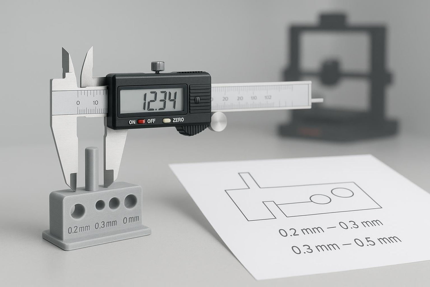
Step 2: print a small tolerance coupon (not your full project)
Don’t test on your full enclosure. Print a small piece that includes:
- one peg and one matching hole
- one “lid-like” sliding interface (optional)
- at least three variants (example: 0.2 mm, 0.3 mm, 0.4 mm)
Done when: you can assemble/disassemble the coupon the way you want, without forcing it.
Step 3: diagnose the failure mode before you change the number
When a fit is wrong, don’t immediately change the CAD clearance. First ask why.
If it’s too tight
Check these in order:
- Elephant’s foot: does the bottom edge catch or flare?
- Over-extrusion: are edges slightly blobby, corners rounded, holes smaller than expected?
- Hole geometry: are you relying on tiny perfect circles (hard for FDM)?
Then choose the smallest fix that solves it:
- Add chamfers/lead-ins.
- Enable slicer elephant’s foot compensation.
- If everything is still tight, increase clearance by +0.1 mm.
If it’s too loose
- Reduce clearance by -0.1 mm.
- Double-check you didn’t accidentally use per-side numbers as total.
- If the looseness comes from flex (thin walls), the fix might be stiffness, not tolerance.
Step 4: make your design tolerant of small errors
Beginners often design “perfect geometry” that assumes a perfect printer. Instead, design interfaces that self-correct:
- Add chamfers and fillets so parts guide themselves into place.
- Avoid sharp internal corners where blobs like to accumulate.
- Prefer longer engagement over tighter engagement (a longer lid lip with 0.4 mm clearance beats a short lip with 0.2 mm).
Step 5: lock your number into FreeCAD (so you stop re-learning it)
In FreeCAD, the easiest way to stop retyping tolerances is to drive them from a Spreadsheet.
Create a spreadsheet and define variables like:
-
clearance_total = 0.4 mm(sliding) -
clearance_total_snug = 0.2 mm(snug)
Then in your sketches:
- Hole diameter =
pin_diameter + clearance_total
Or if you prefer per-side reasoning:
clearance_per_side = 0.2 mm- Hole diameter =
pin_diameter + 2 * clearance_per_side
Done when: you can change one cell and your whole model updates.
Key Takeaway: The fastest path to “perfect tolerance every time” is a parametric tolerance variable + a 20-minute test coupon. After that, your designs get easier.
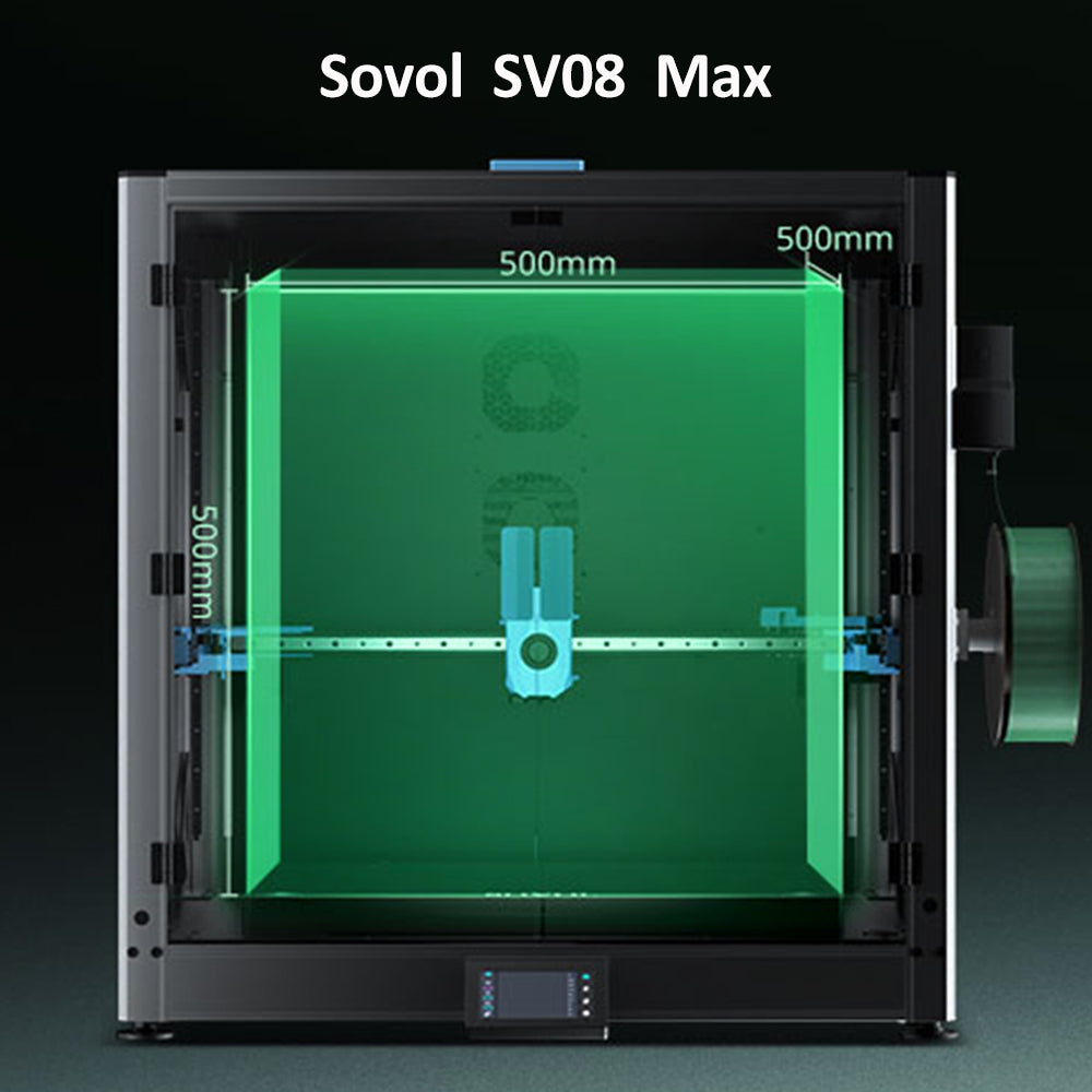
A quick note on printer choice (using Sovol as a practical example)
You can run this workflow on basically any FDM printer. Where your machine does matter is repeatability: stable first layers, consistent extrusion, and not shaking itself loose.
If you’re running a Sovol printer, treat this article as your design method, then make sure your printer setup is stable. A simple routine like Sovol’s guide on tests to run before printing for reliable results can help you get more consistent fits from print to print.
Also, if you keep chasing fit issues while printing very fast, slow down for your functional parts. Sovol’s overview of how print speed affects dimensional accuracy explains why.
Keyword quick hits (so you can find this later)
If you’re searching for this topic later, you’ll see it phrased a few ways. They all point to the same problem:
- FDM clearance fit: choosing a gap so parts can move without binding.
- snap fit 3D printing tolerance: designing clips so they assemble once (or many times) without cracking.
- hole undersized 3D print: the reason screws don’t go in and pegs jam.
FAQ
What tolerance should I use for parts that need to slide?
Start with 0.3–0.5 mm total clearance, then adjust in 0.1 mm steps based on a small test coupon.
Is PLA or PETG better for snap fits?
PETG is usually more forgiving because it’s tougher and can flex more. PLA is stiffer and can crack in thin clips. If you want a stricter, material-specific starting point (including per-side values), use the Voxel Magic guide referenced earlier.
My pegs fit, but screws don’t—why?
Holes behave differently than outer dimensions. Screws also self-tap and need a clean entry. Add chamfers, check for elephant’s foot near the base, and test your hole sizes with a small coupon before committing to the full part.
Should I fix fit issues in CAD or in the slicer?
- Use CAD clearances + chamfers for one-off interfaces (more robust).
- Use slicer XY/horizontal compensation when everything is globally tight/loose.
What’s a realistic tolerance expectation for a home FDM printer?
It depends on printer, settings, and part geometry, but it’s normal to design with “a few tenths of a millimeter” of wiggle room in FDM. Xometry’s overview of typical tolerance ranges for 3D printing processes is a useful expectation-setter.
Next steps
If you want one practical next move: design and print a tiny peg-and-hole coupon with 0.2, 0.3, and 0.4 mm total clearances, then save your winner as a FreeCAD spreadsheet variable. That single habit will pay you back on every functional print you do.