

You’re staring at a CAD model that’s “basically done.” Now comes the uncomfortable question: what process should this part be made with?
If you pick the process too late, DFM turns into damage control. If you pick it early (while the geometry is still flexible), you can save weeks of iteration and a surprising amount of cost.
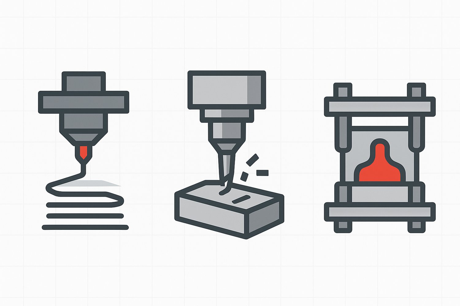
This guide compares 3D printing vs CNC vs injection molding from a designer’s perspective, with design for manufacturing (DFM) constraints you can apply to a real CAD model.
Quick comparison matrix (designer view)
|
Criterion |
3D printing (additive) |
CNC machining (subtractive) |
Injection molding |
|---|---|---|---|
|
Best when |
Complex geometry, fast iteration, low volume |
Tight tolerances, great finish, real material properties |
High volume, lowest unit cost after tooling |
|
DFM “gotcha” that surprises teams |
Layer direction and supports change strength and surfaces |
Tool access and internal corners force geometry changes |
Draft, parting line, and uniform walls control everything |
|
Typical quantity bands (directional) |
Often used for 1–50+ parts |
Often used for 1–200+ parts |
Often used for 25–10,000+ parts |
|
Lead time (directional) |
Days to ~1 week |
Same day to a few days for many parts |
More time upfront due to mold/tooling |
The quantity and lead-time ranges vary by supplier, material, and geometry, but the “shape” of the decision is consistent. Protolabs’ overview is a good reference point for how service bureaus frame the trade-offs.
How to choose 3D printing vs CNC vs injection molding
Most teams start with cost. Designers should start with the constraint that will cause a re-design if you’re wrong:
- If you need tight tolerances or precision fits, CNC is often the shortest path.
- If you need high volume, injection molding is usually where you end up.
- If the part is still changing weekly, 3D printing buys you iteration speed and geometric freedom.
Then use the sections below to pressure-test your choice with DFM reality.
Geometry and feature access
3D printing
3D printing can produce shapes that are annoying or impossible to machine: internal channels, lattices, organic surfaces, one-off custom features. The price you pay is usually support strategy and post-processing.
A practical rule of thumb is that many designs start needing supports once you exceed roughly a 45° overhang, depending on process and material. If you want a quick refresher (and a handy internal resource for your readers), Sovol’s explainer is a clean starting point: 45-degree design rule. For an external reference, Wevolver gives a similar framing in its 3D printing overhang guide.
Designer move: If a surface matters cosmetically or functionally, orient the part so that surface is not a “supported” face.
CNC machining
CNC doesn’t care how wild your CAD looks. It cares whether a cutter can reach it.
If a standard rotating tool can’t access a feature in a straight shot, you’re looking at multi-axis work, special tooling, or a design change. Hubs calls out tool access and workholding as core CNC constraints in its CNC machining guide.
Designer move: Ask yourself “how would a cylindrical cutter touch this surface?” early. If you can’t sketch a tool path, you’re probably forcing a redesign.
Injection molding
Injection molding is brutally good at repeating a shape. But the shape has to be compatible with the mold.
The two geometry constraints that drive most rework are:
- Draft direction (the part has to release)
- Undercuts (anything that traps the part in the tool)
If you don’t want surprises, you decide pull direction, parting line, and where you can tolerate witness lines early.
CNC machining tolerances and fit: what “precision” really means by process
Tolerance needs often masquerade as “quality.” They’re not the same. A part can look gorgeous and still be wrong if your mating features drift.
CNC machining usually wins tight fits
If the part includes bearing seats, press fits, critical alignment features, or sealing surfaces, CNC tends to be the default because it can reliably hit tight tolerances and maintain good surface finish. Hubs’ comparison of the two processes highlights CNC’s advantage for accuracy and surface quality in its 3D printing vs CNC article.
3D printing tolerances vary by technology
This is where designers get burned: “3D printing” is not one tolerance profile.
- Desktop FDM behaves differently from industrial FDM.
- SLA behaves differently from SLS.
- Post-processing (sanding, vapor smoothing) changes dimensions.
If you’re specifying small holes, thin snap features, or critical fits, pull tolerance guidance from a process-specific source. Formlabs provides a clean process breakdown in Formlabs’ minimum wall thickness guidelines, which also helps you reason about which features are even printable.
Designer move: Prototype the fit the same way you’ll manufacture it. “Printed fit” and “machined fit” can be two different parts.
Injection molding can be consistent, but shrinkage is part of the design
Molded parts can be repeatable, but they also live in a world where resin shrinkage, cooling, and mold design are part of the final dimension story.
If you’re doing injection molding, expect to iterate the tool (or at least the process) to dial in critical dimensions.
Surface finish: where you pay for beauty
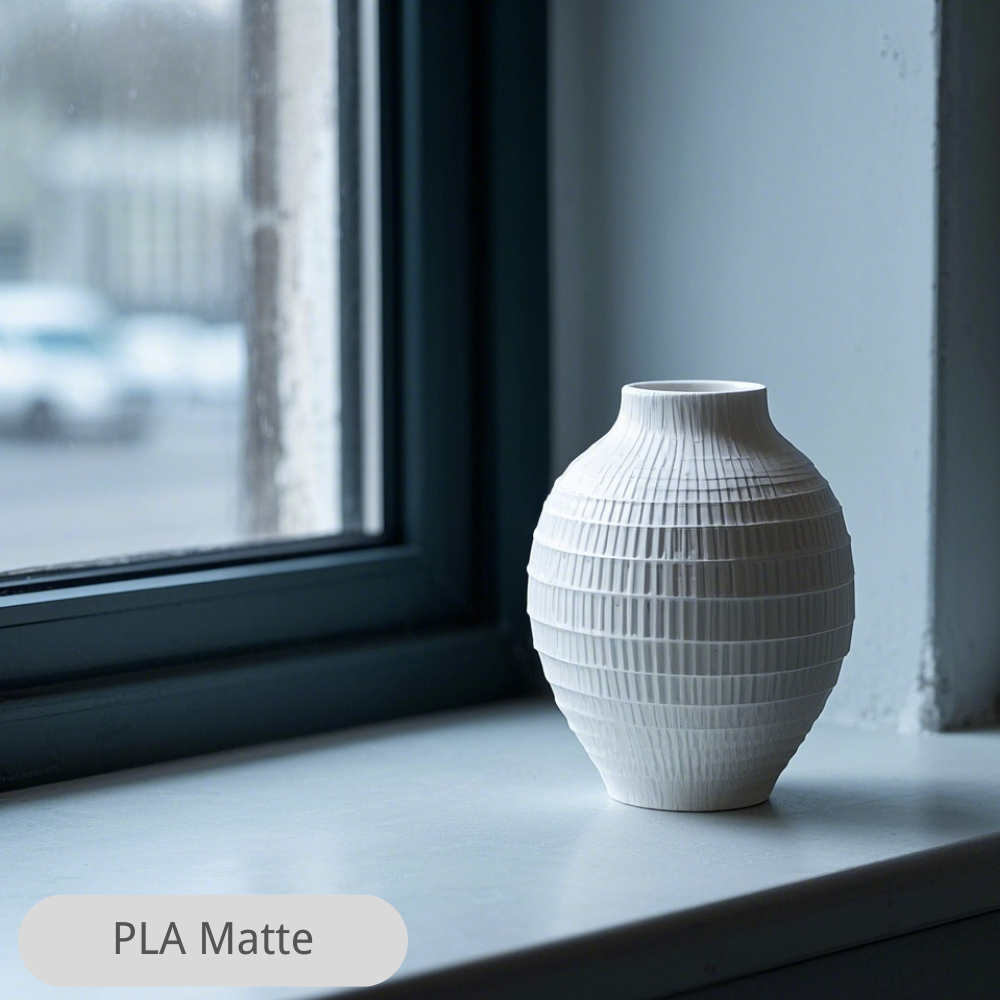
3D printing
Layer lines aren’t just cosmetic. They affect friction, sealing, and how a part feels in the hand. Getting a smooth surface often means sanding, coating, or vapor smoothing.
Designer move: If you need a smooth “consumer touch” surface, consider designing a cosmetic shell to be molded later, or route only the high-touch surfaces through a finishing step.
CNC machining
CNC gives you a predictable finish and sharp detail, especially on external faces. But internal corners will always be radiused, and tool marks are real.
If you want a consistent finish without paying for polishing, design with larger internal radii. Xometry’s machining tip explains why radii sizing affects cost and stability in Xometry’s internal corner radii tip.
Injection molding
Injection molding is where you can get repeatable cosmetic surfaces at scale. Texture, gloss, and consistent appearance are part of the process.
The trade-off is you’re now designing for a tool. You don’t get to pretend the parting line doesn’t exist.
3D printing wall thickness, ribs, bosses, and support strategies
This section is where DFM stops being theory and starts being CAD edits.
Injection molding rewards uniform walls
Uniform wall thickness helps control cooling, warpage, and sink marks. Many DFM guides put typical wall thickness ranges in the ~1–5 mm band depending on resin and part requirements, with a strong preference for consistency. Fictiv’s explainer is a solid overview: Fictiv’s wall thickness guidance for injection molding.
Designer move: If you need stiffness, don’t just thicken the wall. Use ribs. Thicker walls can create cosmetic defects and longer cycles.
3D printing rewards “where you put material” thinking
In additive, you can trade bulk for structure. Instead of thick walls everywhere, you can use:
- local thickening only where load enters
- ribs and gussets
- infill choices (for FDM)
If you’re designing for functional prototypes, material selection matters as much as geometry. For internal reading, Sovol’s material strength breakdown can help readers make more informed choices: Strength of common 3D printing filaments.
CNC machining punishes thin, tall features
Thin walls and deep pockets can chatter, deflect, or demand tiny tools that drive cost. When possible, keep features stout enough to be machined with larger cutters.
Designer move: If a feature must be thin, consider splitting the part and joining it, or shifting the thinness to a molded part later.
Undercuts, draft, and the parting-line reality (injection molding)
If you remember only one injection molding rule, make it this: the part has to come out of the tool.
Draft angles aren’t optional
A common rule of thumb is around 1.5–2° draft per side for many parts (more for textured surfaces), because it reduces drag marks and ejection issues. See Fictiv’s injection molding draft angle guidelines for a practical breakdown.
Undercuts are either removed or paid for
Undercuts can require slides, lifters, or secondary operations. Sometimes that’s the right decision. Often it’s not.
Designer move: If a single snap feature causes a side action, ask whether you can redesign the snap, rotate the pull direction, or split the part.
Mechanical performance: isotropic vs “depends on orientation”
CNC machining
Machined parts inherit the parent material’s properties. For functional testing, that matters.
Injection molding
Molded parts are generally consistent and strong for their resin family, and they’re predictable across runs once dialed in.
3D printing
In many 3D printed parts, strength depends on layer direction. The same design can behave like a tough bracket or a brittle stack of pancakes depending on orientation.
Designer move: Treat print orientation as part of the design spec when the part is load-bearing.
Speed, iteration, and production ramp
DFM decisions change across the lifecycle:
- Prototype phase: 3D printing is often the fastest way to learn.
- Functional test and pilot builds: CNC can be the fastest way to get “real” materials and tight fits.
- Scale: injection molding is usually how you get unit cost down and quality consistent.
Protolabs lays out this lifecycle framing in its process selection overview.
Cost drivers designers can control (DFM levers)
Designers don’t control resin pricing or shop rates. You control the geometry that creates time, risk, and tooling cost.
If you’re 3D printing
- Reduce supports by reorienting and redesigning overhangs.
- Avoid surfaces that require heavy finishing.
- Batch parts if the process allows it.
If you’re machining
- Increase internal corner radii where possible.
- Avoid deep, narrow cavities that force small tools.
- Don’t specify ultra-tight tolerances everywhere. Make only the truly critical dimensions tight.
If you’re molding
- Design for a simple pull direction.
- Keep walls uniform and use ribs.
- Avoid undercuts that require slides.
For the cost vs tooling logic behind high-volume molding, Protolabs’ discussion of piece-part price is a helpful reference: Protolabs’ cost comparison for injection molding vs 3D printing.
A practical decision flow (use this on a real part)
For a broader process-level overview, see Protolabs’ guide to selecting a manufacturing process.
If you want a quick path without overthinking it:
- Is your production volume likely to be high enough to justify tooling? If yes, start designing with injection molding constraints (draft, parting line, uniform walls).
- Do you need tight fits or real material behavior right now? If yes, CNC is usually the quickest way to de-risk.
- Are you still iterating geometry weekly? If yes, start with 3D printing and design for supports/orientation so prototypes teach you what you need.
- Does the design contain features that are unmachinable or extremely expensive to machine? If yes, prefer 3D printing for early builds or redesign for CNC.
- Does molding require slides for one small undercut? If yes, redesign that feature before committing.
Next steps
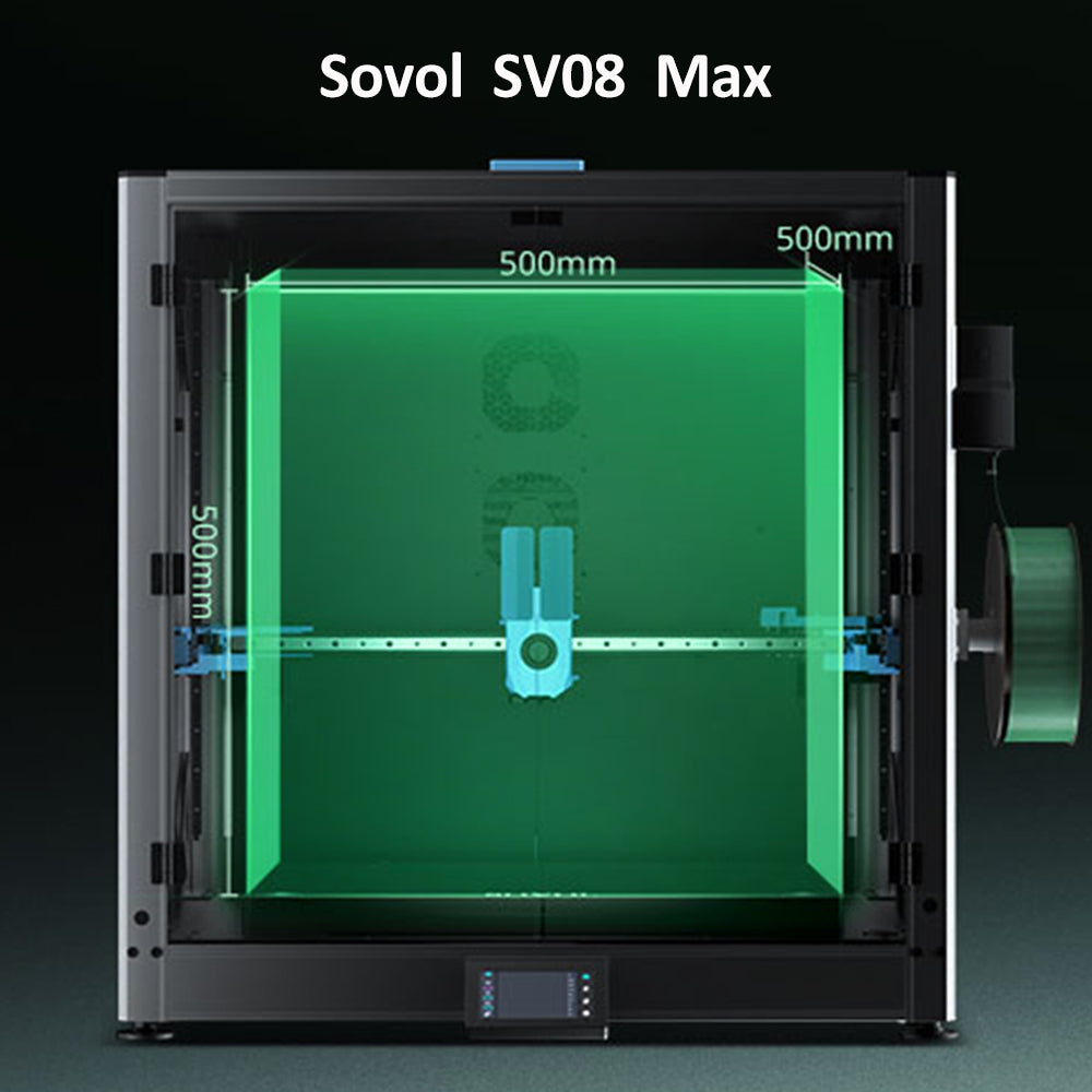
If your next build is likely to be additive, it helps to pick a printer that matches the part size and material you’re designing around. You can browse Sovol for 3D printer options, then use this DFM checklist to pressure-test your geometry before you commit.
If you’re deciding between a few candidate designs, run the same part through three quick “what would break” passes:
- What would require supports (3D printing)?
- What can’t a cutter reach (CNC)?
- What won’t release from a mold (injection molding)?
That exercise tends to surface the redesign you’ll eventually need anyway.