


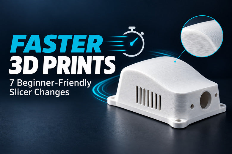
A long print does not always need a faster printer. In many cases, a few sensible slicer changes can remove hours from the estimate without making the finished part look noticeably worse.
The safest approach is not to push every speed value to the maximum. Instead, reduce work the printer does not need: use an appropriate layer height, avoid excessive infill, place the model intelligently, and keep supports under control.
This beginner-friendly guide covers seven practical ways to shorten FDM print time while protecting surface quality, strength, and reliability.
Why does a 3D print take so long?
A slicer turns a 3D model into hundreds or thousands of toolpaths. Print time grows when the printer has to create more layers, travel through more internal material, print large support structures, or repeatedly slow down for small features and corners.
The speed number shown in a printer specification is only one part of the picture. A small model with many short movements may never reach that speed. Layer height, wall count, infill, acceleration, cooling and the model itself can matter just as much.
Before changing anything, slice the model with a trusted default profile and save the estimated time. This gives you a baseline for comparison.
1. Increase layer height before increasing print speed

Layer height is often the first setting worth checking. Taller layers mean the printer needs fewer layers to reach the same model height.
For example, changing from a very fine 0.12 mm profile to a standard 0.20 mm profile can make a large difference to the estimate. A 0.28 mm profile may save even more time when the installed 0.4 mm nozzle and printer profile support it.
The trade-off is more visible layer stepping, especially on shallow curves and rounded tops. Vertical walls are usually affected much less.
Use the tested presets supplied for your printer and nozzle. As a general upper limit, layer height should remain below about 80% of the nozzle diameter. For a 0.4 mm nozzle, that is approximately 0.32 mm, but the approved range in your actual printer profile takes priority.
A simple choice
- Choose a fine preset for miniatures, small text and important curved surfaces.
- Choose a standard preset for everyday parts and prototypes.
- Choose a draft preset for large test pieces where speed matters more than layer visibility.
2. Use only as much infill as the part needs
Higher infill creates more internal toolpaths, so it normally increases both print time and material use. Many decorative models and lightly loaded parts can start around 10–15% infill, but this is not a universal strength setting.
Do not automatically use 50% or 100% infill because a part needs to be strong. For many FDM parts, adding suitable outer walls is more useful than filling the entire interior with plastic. Infill still matters for compression resistance, top-surface support and overall stiffness.
Always consider the real load:
- A display model usually needs little internal material.
- A housing may need moderate infill and reliable walls.
- A bracket under load needs the correct orientation, material and wall structure—not just a higher infill percentage.
3. Balance walls, top layers and infill

Reducing walls and solid top or bottom layers can save time, but these settings should not be lowered blindly.
Walls create the outside shape and contribute strongly to part strength. Top layers close the model over the infill. If there are too few, the top surface may sag or show gaps.
Start with the tested profile for your printer. If the part is only decorative, you may be able to use a lighter wall and infill setup. For a functional part, keep enough wall thickness for the expected load and enough top thickness to close the surface cleanly.
Compare total thickness rather than layer count alone. Four top layers at 0.20 mm create 0.80 mm of material, while four layers at 0.10 mm create only 0.40 mm.
4. Rotate the model to reduce supports

Support material adds toolpaths, travel moves and cleanup. Before changing dozens of support settings, try rotating the model.
A better orientation can:
- place a broad, stable surface on the build plate;
- turn difficult overhangs into printable slopes;
- reduce the height of the model and therefore the number of layers;
- keep support marks away from visible surfaces.
Orientation also changes strength because FDM parts are usually weaker between layers than along continuous extrusion paths. The fastest orientation is not always the strongest one. Check the direction of the expected load before printing a functional part.
Use support only where it is needed
After choosing the orientation, inspect every support region in the sliced preview. “Support on build plate only,” painted support areas or a suitable tree/organic support style may reduce material in some models.
Do not remove support from a critical overhang simply to shorten the estimate. First test the printer’s overhang and bridging ability with the same material and cooling profile.
5. Use variable layer height for mixed geometry
Some models have long straight walls and only one or two important curved areas. Printing the entire object with fine layers wastes time on the simple sections.
Variable or adaptive layer height allows the slicer to use thinner layers on shallow curves and thicker layers on steep walls. It is especially useful for helmets, rounded covers, figures and curved housings.
Use the automatic calculation as a starting point, smooth abrupt transitions and check the final layer preview. This feature mainly improves resolution in the Z direction; it does not replace a smaller nozzle when the model contains very narrow XY details.
6. Consider a larger nozzle for large parts
A 0.6 mm nozzle can print wider lines and use taller layers than a 0.4 mm nozzle. On large functional parts, this can reduce the number of wall paths and layers.
A larger nozzle does not guarantee a proportional speed increase. Wider and taller extrusion lines require the hotend to melt more plastic every second. The slicer may reduce the actual speed when it reaches the maximum volumetric flow allowed by the hotend and filament profile.
A larger nozzle is most useful when:
- the model is large and does not contain very fine details;
- wider functional walls are more important than a delicate surface;
- the printer has a tested profile for that nozzle size;
- the hotend and material can provide the required flow reliably.
After changing the nozzle, select the matching printer and process profile. Never print G-code prepared for a different nozzle diameter.
7. Increase speed gradually—not all at once
Only after reducing unnecessary layers, infill and support should you consider raising print speeds.
Different parts of the model do not need the same speed. Internal infill can often print faster than visible outer walls. Bridges, overhangs, small details and the first layer may need slower, more controlled movement.
Increase speed in small steps and watch for:
- thin lines or gaps caused by under-extrusion;
- ringing after corners;
- weak layer bonding;
- poor bridges and overhangs;
- extruder clicking at high-flow sections.
If a requested speed does not reduce the estimate, another limit may already be active. Acceleration, minimum layer time, overhang speed or maximum volumetric flow can all limit the real movement speed.
The safest order for reducing print time
- Slice the model with a trusted default profile and record the estimate.
- Choose the coarsest layer-height preset that still provides the surface you need.
- Reduce excessive infill while keeping the required wall strength.
- Rotate the model and reduce unnecessary support.
- Use variable layer height if only a few areas need fine layers.
- Consider a larger nozzle for large, simple parts.
- Increase speed only in small steps and verify the result with a test print.
Change one major setting at a time and slice again. This shows which adjustment actually saves time and prevents several changes from creating a new problem together.
Quick comparison
| Change | Possible time saving | Main trade-off |
|---|---|---|
| Increase layer height | Often high | More visible layer stepping |
| Reduce excessive infill | Medium to high | Lower stiffness or top-surface support if reduced too far |
| Reduce unnecessary supports | Often high | Some overhangs may fail without support |
| Use variable layer height | Model-dependent | Requires careful preview checking |
| Use a larger nozzle | High on suitable large parts | Less fine detail and higher flow demand |
| Raise speed values | Model-dependent | Can reduce quality or exceed flow limits |
Common mistakes
- Changing every speed value: Outer walls, bridges and the first layer often need different limits.
- Using very high infill for strength: Wall structure, orientation and material are often more important.
- Removing all supports: A shorter estimate is not useful if the overhang fails.
- Using the maximum layer height everywhere: Curves and slopes may show obvious steps.
- Ignoring volumetric flow: The hotend may not melt enough plastic for the requested line width, layer height and speed.
- Testing with a long project: Use a small representative section before committing to a multi-hour print.
Checklist before starting a faster print
- The printer, nozzle and filament profiles match the installed hardware.
- The selected layer height is allowed by the nozzle profile.
- Walls and top layers still provide the required thickness.
- Infill matches the part’s actual use.
- The orientation reduces support without weakening the load direction.
- All bridges, overhangs and support contacts have been checked in preview.
- The requested flow remains within the tested profile.
- A small test print has confirmed the important surfaces and dimensions.
Frequently asked questions
What setting usually reduces print time the most?
It depends on the model. Increasing layer height often makes a large difference because it reduces the total number of layers. For models with heavy support, changing orientation may save even more time.
Does doubling print speed cut the time in half?
Usually not. The printer must accelerate, slow down for corners, respect cooling time and stay within the hotend’s flow limit. Many short toolpaths never reach the requested maximum speed.
How much infill should I use?
Many ordinary models can start around 10–15%, but the correct value depends on geometry and load. Functional parts may need different walls, orientation or infill. Do not use one percentage for every model.
Is a 0.6 mm nozzle always faster than a 0.4 mm nozzle?
No. It is often faster for large parts that can use wider lines and taller layers. Small detailed models may gain little, and the hotend’s volumetric-flow limit can restrict the actual speed.
Should I reduce walls or infill first?
For many functional parts, keep appropriate walls and reduce clearly excessive infill first. Walls often contribute strongly to strength, while infill mainly supports the interior and top surfaces. Always test parts that carry a real load.
Why did the estimate barely change after I increased speed?
The print may already be limited by acceleration, minimum layer time, overhang settings or maximum volumetric flow. Use the slicer’s speed and flow previews to find the active limitation.
Conclusion
The best way to shorten a 3D print is usually to remove unnecessary work before pushing the printer harder.
Start with layer height, infill and model orientation. Keep enough walls and solid layers for the part’s real purpose, and use supports only where the geometry needs them. Variable layer height and a larger nozzle can provide additional savings on suitable models.
Finally, increase speed gradually and confirm the result with a small test. A faster estimate only matters when the finished part still has the surface quality, dimensions and strength you need.
